 Veronte
Unit name
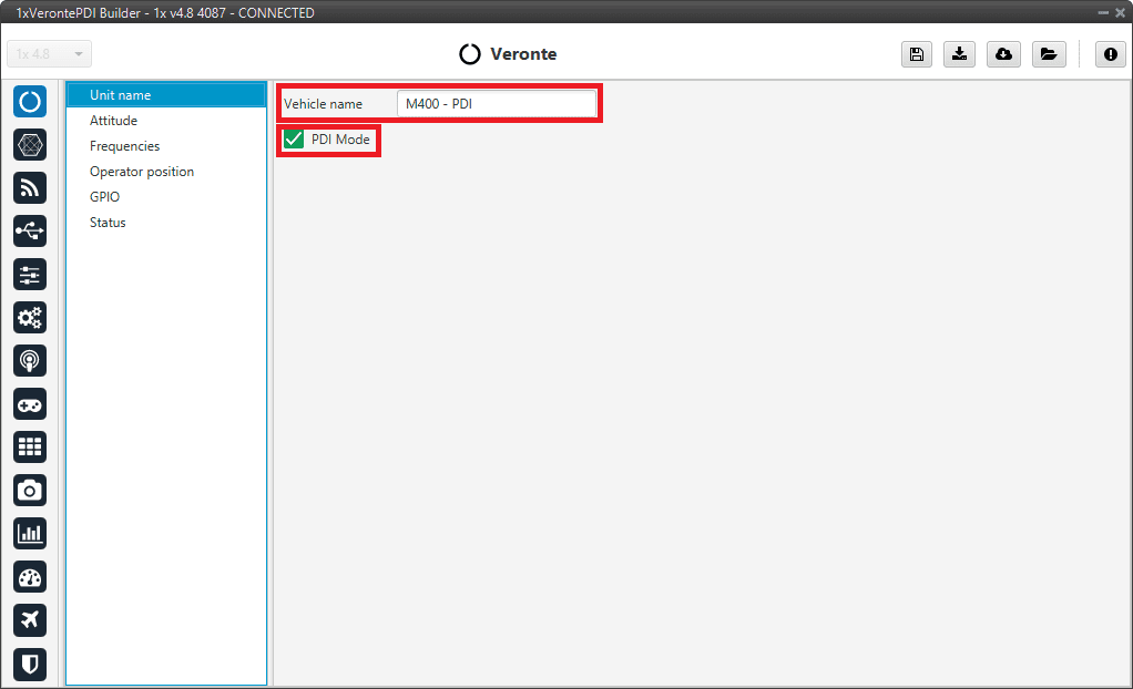
Unit name panel
Vehicle name: The user can define the name of the configuration.
PDI Mode: It can be enabled or disabled. PDI mode allows the user to change the setup if Autopilot 1x is not in INI phase.
Warning
Not being in PDI mode, users cannot perform the following actions if they are not in INI phase:
Reboot Autopilot 1x
Change 1x setup (i.e. save to SD card)
Enter manually in maintenance mode
The variable ‘System error’ prevents operation in normal mode (not PDI mode). A list of all errors that can cause this bit to be set can be found in the Activation System Error bits section of the 1x Software Manual.
If Autopilot 1x has ‘sensors errors’ and is in normal mode (not PDI mode), the user will not be able to switch to another flight phase, it will remain in INI phase.
Danger
PDI mode is intended for development purposes since, as detailed above, it allows flight phase changes with system, sensor and PDI errors.
It is highly recommended to limit its use to simulation and ground testing of peripherals during the development phase.
Therefore, as it is not advisable to operate in PDI mode, please disable it once the configuration is finished and intended to be used in flight.
Attitude
This menu allows the user to define the orientation of the autopilot with respect to the platform once it is installed. Aircraft axis are defined according to international aviation convention. Autopilot 1x axis are drawn on the autopilot’s external case as defined in the Orientation - Hardware Installation section of the 1x Hardware Manual.
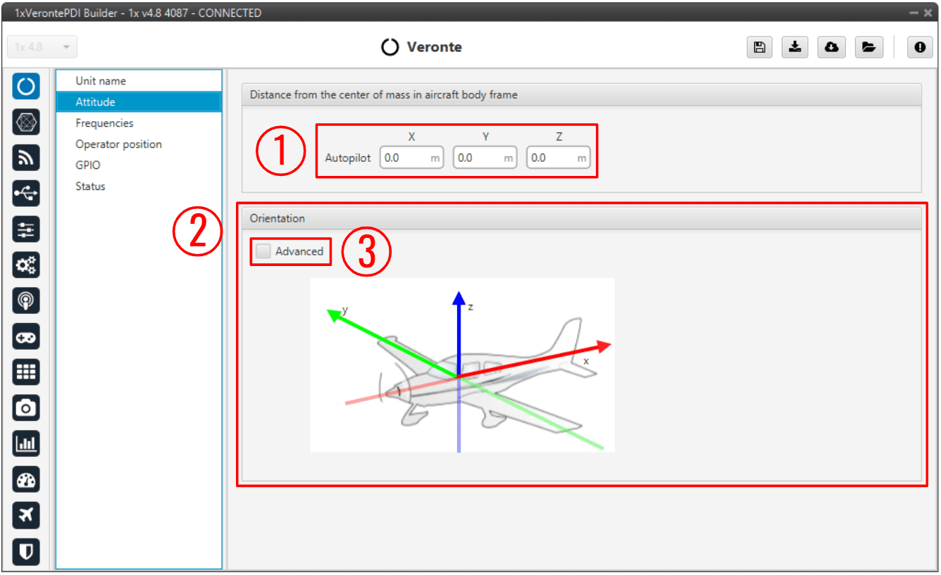
Attitude panel
Distance from the center of mass in aircraft body frame: The autopilot’s distance from the center of mass must be defined. This distance is entered in meters and accordingly to aircraft axis.
If the autopilot is not located in the center of mass, it will measure a non-zero acceleration when turning. Distance from the center of mass in aircraft body frame is used to compensate this value. An example is presented below:
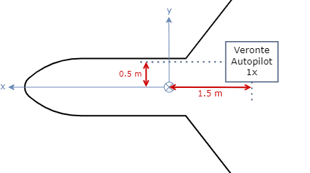
Distance from the center of mass in aircraft body frame - Example
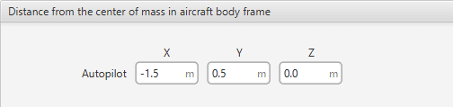
Distance from the center of mass in aircraft body frame - Example
Orientation: It is not compulsory to install the autopilot aligned with the aircraft axis. In order to indicate the autopilot’s relative position inside the platform, select the advanced option (3). A matrix relating vehicle axis and autopilot axis is needed to be filled in. The case of a non-orthogonal installation can be covered.
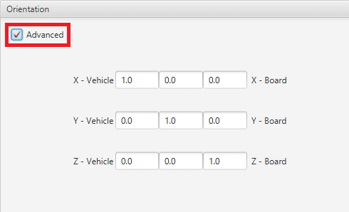
Advanced orientation
Note
If only a simple rotation is required, for example, a -90º rotation in the Z axis, it is simpler to select the correct axis directly in the ‘plane’:
Change orientation
Frequencies
The frequency of the GNC task refers to the maximum working frequency of the core. In this case, 400 Hz, which is the maximum possible.
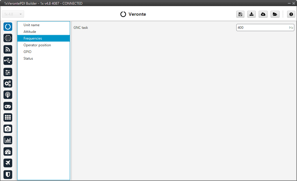
Frequencies panel
Warning
400 Hz can be used only for simple configurations, so it is often necessary to reduce the frequency to 250-300 Hz. To find out why the user should reduce the GNC Task frequency, see Reduce GNC Task frequency - Troubleshooting section of this manual.
Operator position
Veronte Autopilot 1x has a limited-operation firmware. The distance allowed by the license is calculated from the operator position.
For more information on this limitation, please refer to the Limited Operation Firmware - Quick Start section of the 1x Hardware Manual.
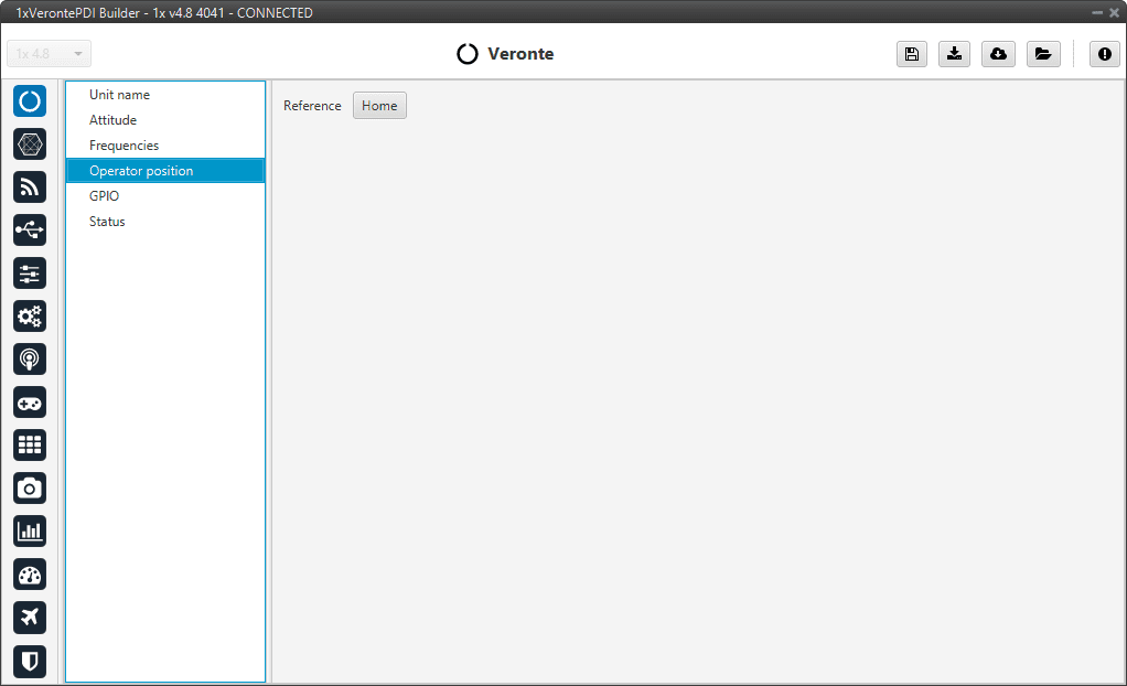
Operator position panel
Tip
In operation, if the air unit does not have the license activated, it is recommended to set the position of the ground unit as the operator position in the air unit.
GPIO
In this tab each individual GPIO behavior can be configured:
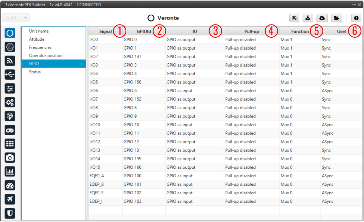
GPIO panel
Signal: Pin ID as described in Pinout - Hardware Installation section of the 1x Hardware Manual.
GPIOId: GPIO ID of the microcontroller.
IO: Define GPIO as an input or output.
Pull-up: Enable or disable the pull-up resistance.
Function: Mux 0: GPIO, Mux 1: PWM, Mux 2, Mux 3, etc. These are the different functionalities that the GPIO can have, this depends on the multiplexer.
Note
When users set Function to “Mux 1”, it indicates that the corresponding pin is disabled as GPIO and enabled as PWM. Consequently, when saving this change, the corresponding PWM pin of the PWM panel should automatically be added as PWM and “disappear” as GPIO.
This behavior also happens the other way around, i.e. when switching from PWM (Mux 1) to GPIO (Mux 0).
Warning
Once the change has been saved, check that the corresponding PWM pin has been added to the PWM panel or that the corresponding GPIO pin has been added to the GPIO panel, depending on the change that has been made.
Qsel: This is the “input qualification”, it is used to control how the value of a GPIO is evaluated. The available options are:
Sync: The value is taken as whatever is present at the time it is checked (synchronously). This is the default mode of all GPIO pins.
3 Samples: The value is checked 3 times and the value is only changed when the 3 times are the same.
6 Samples: Same as before, but checking 6 times instead of 3.
ASync: No checks are performed. It is used when it is not used as GPIO.
Status
This option enables the periodic sending of the status message that Veronte Link uses to recognize the Autopilot 1x.
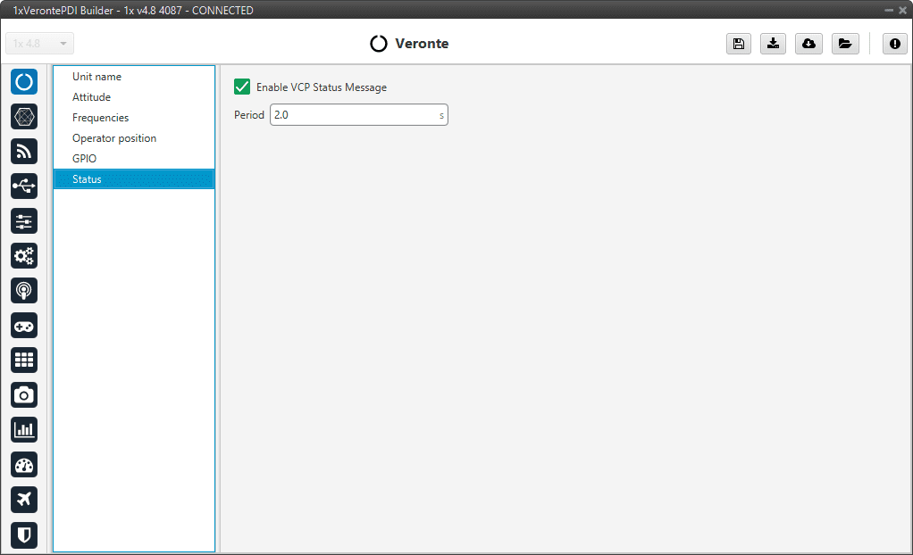
Status panel
Period: Enter a desired period to send repeatedly the status message.
Note
VCP is the Veronte Communication Protocol. To know more, read the VCP user manual.